
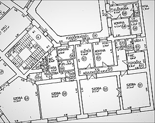
Sample main floor program for a small family home
In compages and building engineering, a floor plan is a technical cartoon to scale, showing a view from above, of the relationships between rooms, spaces, traffic patterns, and other physical features at one level of a construction.
Dimensions are usually drawn between the walls to specify room sizes and wall lengths. Floor plans may too include details of fixtures like sinks, water heaters, furnaces, etc. Flooring plans may include notes for structure to specify finishes, construction methods, or symbols for electrical items.
It is besides called a plan which is a measured plane typically projected at the flooring height of 4 ft (1.2 m), as opposed to an elevation which is a measured plane projected from the side of a edifice, along its top, or a department or cantankerous department where a building is cut along an axis to reveal the interior structure.
Overview [edit]
Like to a map, the orientation of the view is downwardly from higher up, merely unlike a conventional map, a plan is drawn at a particular vertical position (unremarkably at near four feet in a higher place the floor). Objects below this level are seen, objects at this level are shown 'cut' in plan-section, and objects above this vertical position within the construction are omitted or shown dashed. Plan view or planform is defined as a vertical orthographic projection of an object on a horizontal airplane, like a map.
The term may be used in full general to describe any cartoon showing the physical layout of objects. For instance, information technology may announce the arrangement of the displayed objects at an exhibition, or the system of exhibitor booths at a convention. Drawings are now reproduced using plotters and large format xerographic copiers.
A reflected ceiling plan (RCP) shows a view of the room as if looking from above, through the ceiling, at a mirror installed one foot below the ceiling level, which shows the reflected image of the ceiling to a higher place. This convention maintains the same orientation of the flooring and ceilings plans – looking downwardly from above. RCPs are used past designers and architects to demonstrate lighting, visible mechanical features, and ceiling forms as function of the documents provided for construction.
The art of amalgam ground plans (ichnography; Gr. τὸ ἴχνος, íchnos, "track, trace" and γράφειν, gráphein, "to write";[i] pronounced ik-nog-rəfi) was first described by Vitruvius (i.two) and included the geometrical projection or horizontal department representing the plan of any building, taken at such a level as to show the outer walls, with the doorways, windows, fireplaces, etc., and the correct thickness of the walls; the position of piers, columns or pilasters, courtyards and other features which constitute the pattern,[2] as to scale.
Floor program topics [edit]
Edifice blocks [edit]

Floor plans use standard symbols to indicate features such as doors. This symbol shows the location of the door in a wall and which mode the door opens.
A flooring plan is non a top view or birds eye view. Information technology is a measured drawing to scale of the layout of a floor in a building. A superlative view or bird'south eye view does not show an orthogonally projected airplane cut at the typical 4 foot height to a higher place the flooring level. A floor programme could show:[3]
- interior walls and hallways
- restrooms
- windows and doors
- appliances such as stoves, refrigerators, water heater etc.
- interior features such equally fireplaces, saunas and whirlpools
- the use of all rooms
Programme view [edit]
A plan view is an orthographic project of a 3-dimensional object from the position of a horizontal plane through the object. In other words, a plan is a section viewed from the acme. In such views, the portion of the object in a higher place the plane (section) is omitted to reveal what lies beyond. In the case of a floor programme, the roof and upper portion of the walls may typically be omitted. Whenever an interior design project is beingness approached, a floor plan is the typical starting signal for any farther design considerations and decisions.
Roof plans are orthographic projections, but they are non sections every bit their viewing plane is exterior of the object.
A plan is a common method of depicting the internal organisation of a three-dimensional object in two dimensions. Information technology is oft used in technical drawing and is traditionally crosshatched. The way of crosshatching indicates the type of fabric the section passes through.
3D flooring plans [edit]
A 3D floor plan can be defined as a virtual model of a building floor plan. It is often used to ameliorate convey architectural plans to individuals not familiar with floor plans. Despite the purpose of floor plans originally being to depict 3D layouts in a 2nd manner, technological expansion has fabricated rendering 3D models much more cost effective. 3D plans show a ameliorate depth of image and are often complemented past 3D piece of furniture in the room. This allows a greater appreciation of calibration than with traditional 2nd floor plans.
Examples [edit]
-

An role plan.
-
Registration flooring programme of a condo (detail)
See also [edit]
- 3D press
- 3D scanner
- Builder'southward calibration
- Architectural drawing
- List of flooring plan software
- Firm
- Business firm plan
- Indoor positioning arrangement (IPS)
- Room number
References [edit]
- ^ T. F. HOAD. "ichnography." The Curtailed Oxford Dictionary of English Etymology. 1996. (Encyclopedia.com. 4 Jan. 2010)
- ^ 1 or more of the preceding sentences incorporates text from a publication now in the public domain:Chisholm, Hugh, ed. (1911). "Ichnography". Encyclopædia Britannica. Vol. 14 (11th ed.). Cambridge University Press. p. 243.
- ^ Site Plans, Elevations and Floor Plans Archived 2010-06-07 at the Wayback Machine A Community Guide San Jose. Accessed 11 February 2009.
External links [edit]
![]() Media related to flooring plans at Wikimedia Commons
Media related to flooring plans at Wikimedia Commons
- Renaissance Visual Thinking: Architectural Representation equally Medium to Contemplate 'Truthful Form', Federica Goffi-Hamilton
DOWNLOAD HERE
How to Draw a Gate on a Floor Plan TUTORIAL
Posted by: apriladven1968.blogspot.com


Comments
Post a Comment